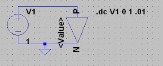
在此,我先說明一下,如何在這個LTspice環境中,基本的使用會用到
Q1.如何加入一個新符號電氣代示
-----------------------------------------
A1:
Creating New Symbols
1. File-->;New Symbol.
2.You draw the body of the symbol as a series of lines, rectangles,
circles, and arcs. The objects have no electrical impact on the circuit.
(沒有何任的電氣意義.)
You can also draw text on the symbol with the
Draw=>Text command that has no impact on the circuit.
3.Adding the Pins
The pins allow electrical connection to the symbol. Use the
menu command Edit=>Add Pin/Port to add a new pin.
The "Pin Label Position" determines how the pin label is
presented.(是pin label是否可見,及位置)
The "Netlist Order" determines the order this pin is netlisted
for SPICE.
4.Adding Attributes
You can define default attributes for a symbol using the menu
command Edit=-->;Attributes=>Edit Attributes
"The most important attribute is called the "Prefix"(其中最重要的參數是prefix)
This determines the basic type of symbol. (決定了symbol的基本種類)
If the symbol is intended to represent a SPICE primitive,
(假如其符號是要去表逹一個spice primitive)
the symbol should have the appropriate prefix, R for resistor, C or capacitor, M for MOSFET, etc.
The prefix should be 'X' if you want to use the symbol to represent
a subcircuit defined in a library.(若其prefix 為"X",代表著其內部是定義在library中一個subcircuit)
其中
prefix---X 表為subcircuit
spicemodel---在那個lib中
Value:
Value2:
If you wish the symbol to represent another page of a
hierarchical schematic, all attributes should be left blank the
symbol type should be changed from "Cell" to "Block". No
attribute values need be set.(若你想要這個symbol是取代另一個page或是hierarchical schematic,並且所有的參數保留空白.並把其symbol type 應該從cell改變成block)
5.
Attribute Visibility (將其相關的參數,顯示出來,可以使用者自己輸入.而不用再去pick)
You can edit the visibility of attributes using the menu command
Edit=>Attributes=>Attribute Window.
A.
B.
C :(使其
(若使用者,輸入正確的Diode的碼號,則此元件就會自動的連結;反之,則你必須自己去連結,pick new diode)
.

6.
Automatic Symbol Generation
A symbol can be automatically generated in two situations.
(A.) (以一個schematic為單位,來建立)
When editing a schematic, you can execute menu item
Hierarchy=>Open this Sheet's Symbol.
(*.需要標示出輸出,輸入埠 出來)
(B).
when editing an ASCII netlist that contains subcircuit
definitions, you place the cursor on the line containing the
name of the subcircuit, right click, and execute context menu
item "Create Symbol".
(*.指在 *.lib中,來建立相對應的符號)
7. Hierarchy
(*你需要將其符號圖及電路圖及你的最上層電路圖,必需要放在同一個資料來中)
The way to refer to another schematic as a block in a higher
level schematic is to create a symbol with the same name as the
block schematic and then by placing that symbol on the higher
level schematic.
================================
Q2.如何加入新的被動元件參數(R,L,C,diode)
step 1.在其元件上面,按右鍵進入編輯
step 2.在其Select Resister按鈕進入
step 3.可以在此中,選擇你所需的電阻等相關的參數
step 4.你也可以在Quit and Edit database按鈕,進入編輯其資料庫
Q3.檔案及資料架構
1.最上層 (主要有其程式的執行檔,說明檔, "lib 資料夾")
2.lib 資料來中(裡面有cmp(基本元件),sub(子電路或libary),sym(電氣符號))
3.cmp資料來中(其中各個檔案,表為一個"資料庫")
裡面均為基本的元件(R,L,C,J,BJT,Diode,MOSFET)
4.sub(子電路及libary.即其ASCII的Spice檔案)
5.sym(電氣符號,可以自己建立符號.但是若你要使用 Hierarchy.則並不需要)


沒有留言:
張貼留言